2N2222 Guitar Pedal (2024)

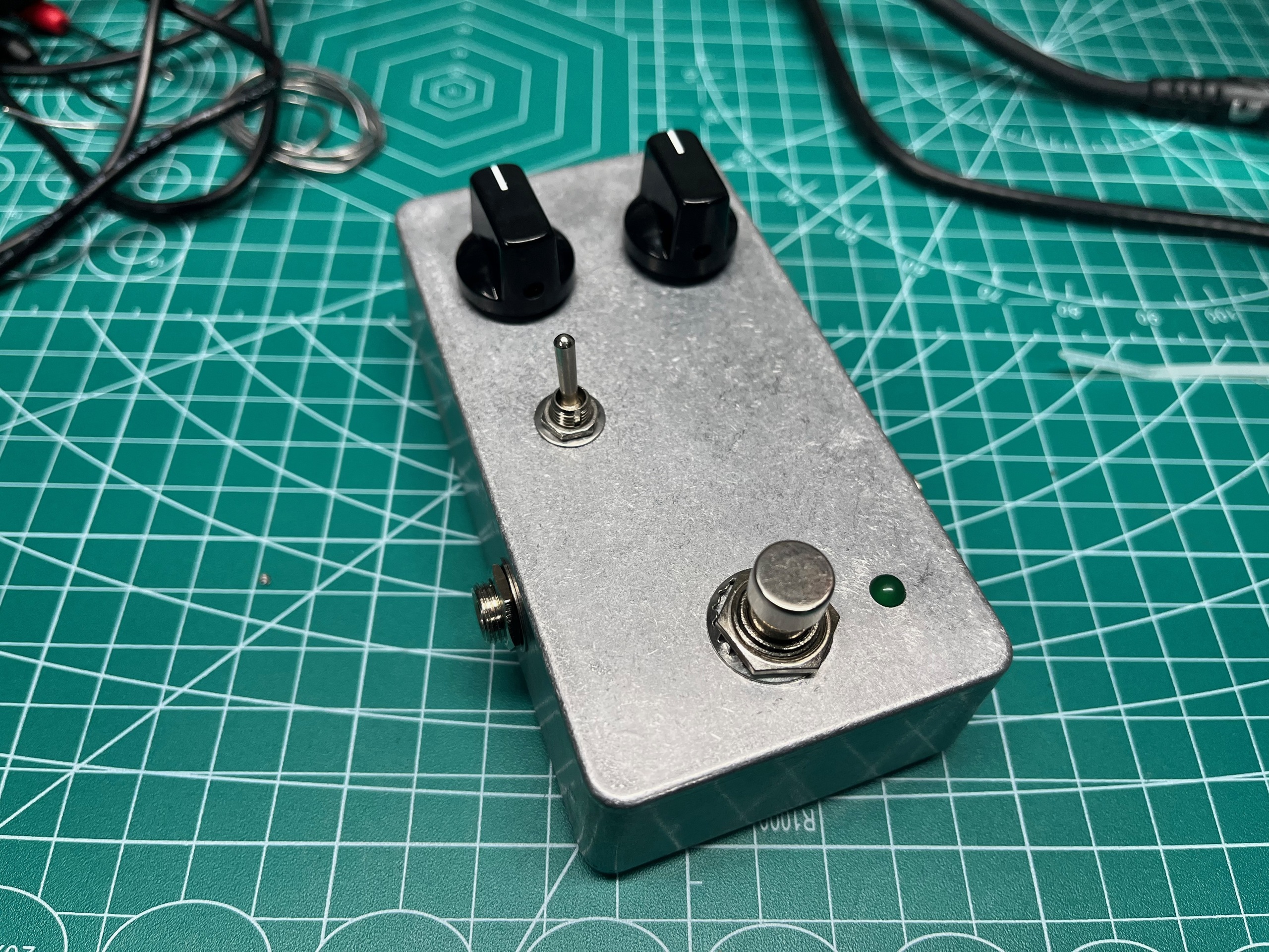
I built a simple single transistor boost pedal with optional diode clipping using parts from my junk drawer, and I'm pretty happy with it!
Max guitar volume, knobs at 12 O'Clock
Diode clipping enabled
Cleans up when guitar volume backed off
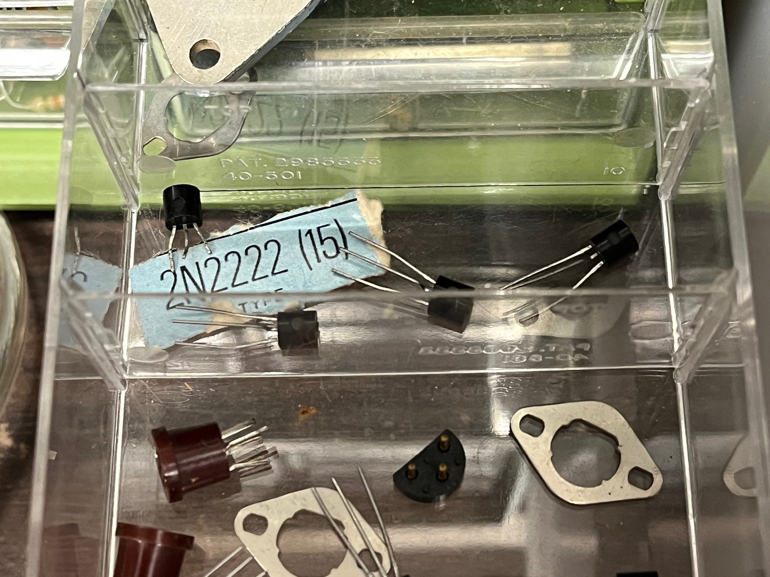
My goal was to better understand how guitar effects pedals are built and to prove to myself that transistors are largely interchangeable and that something interesting could be built with parts on hand.
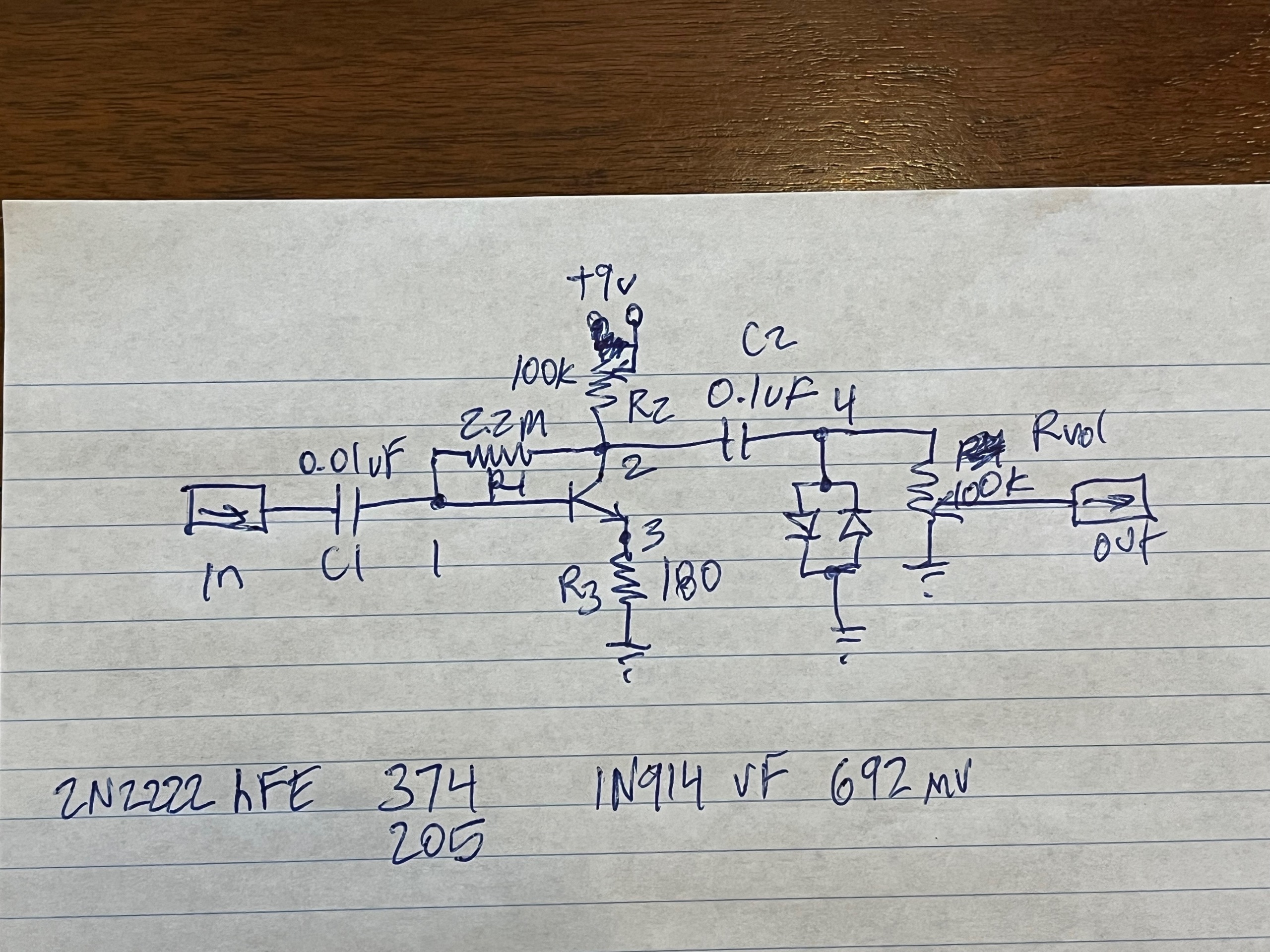
My idea was to build the simplest common-emitter amplifier circuit that I could get away with, something like this "textbook" schematic from Wikipedia, with one of the most boring transistors, the 2N2222
Bypass Wiring
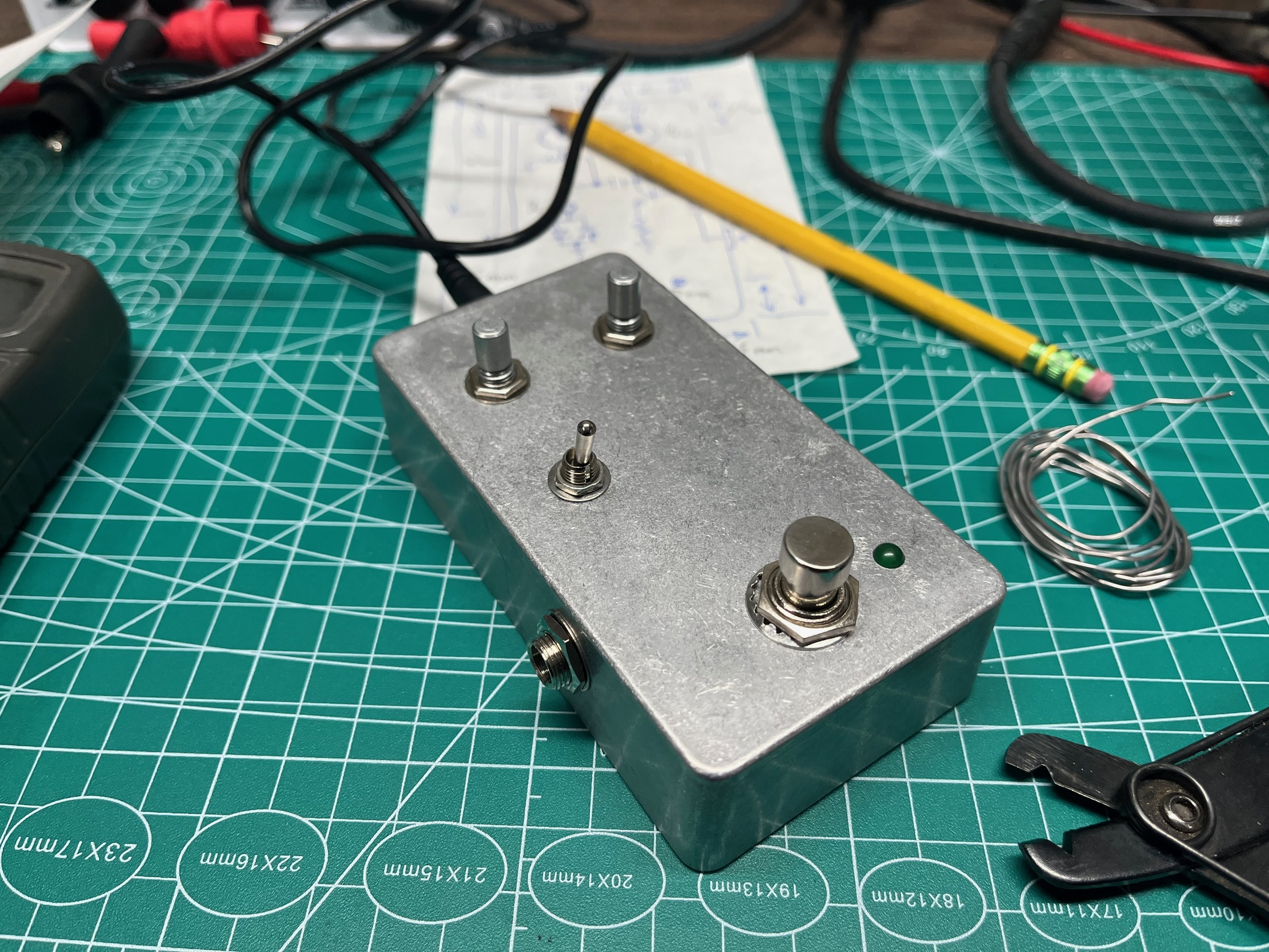
But first, before starting on that, I decided to build an even simpler pedal, a completely passive pedal that could switch an effects loop in and out of the signal path. This would give me a chance to figure out the bypass wiring in isolation and would also, I thought, be useful for patching a breadboarded circuit into the signal path for testing.
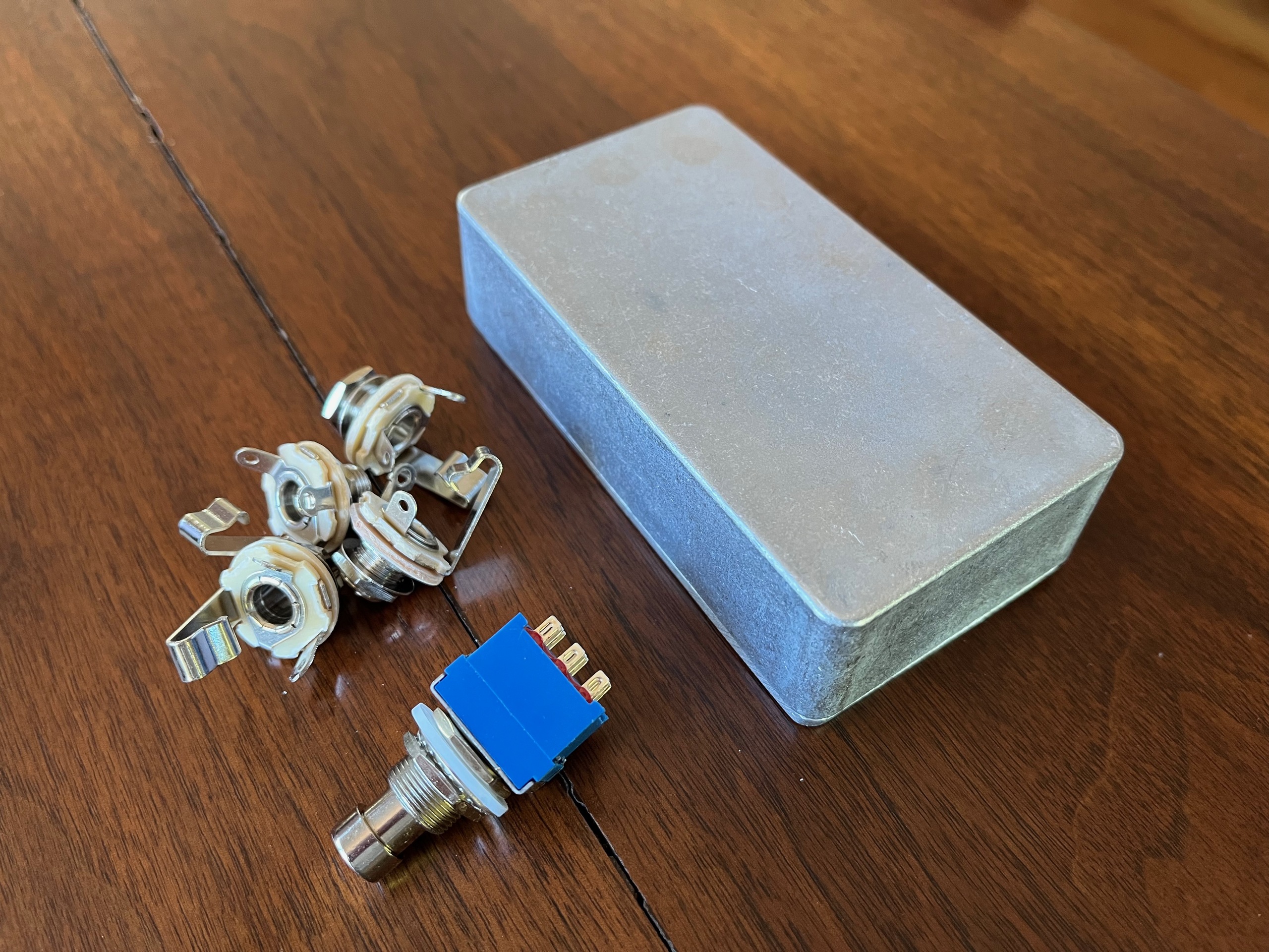
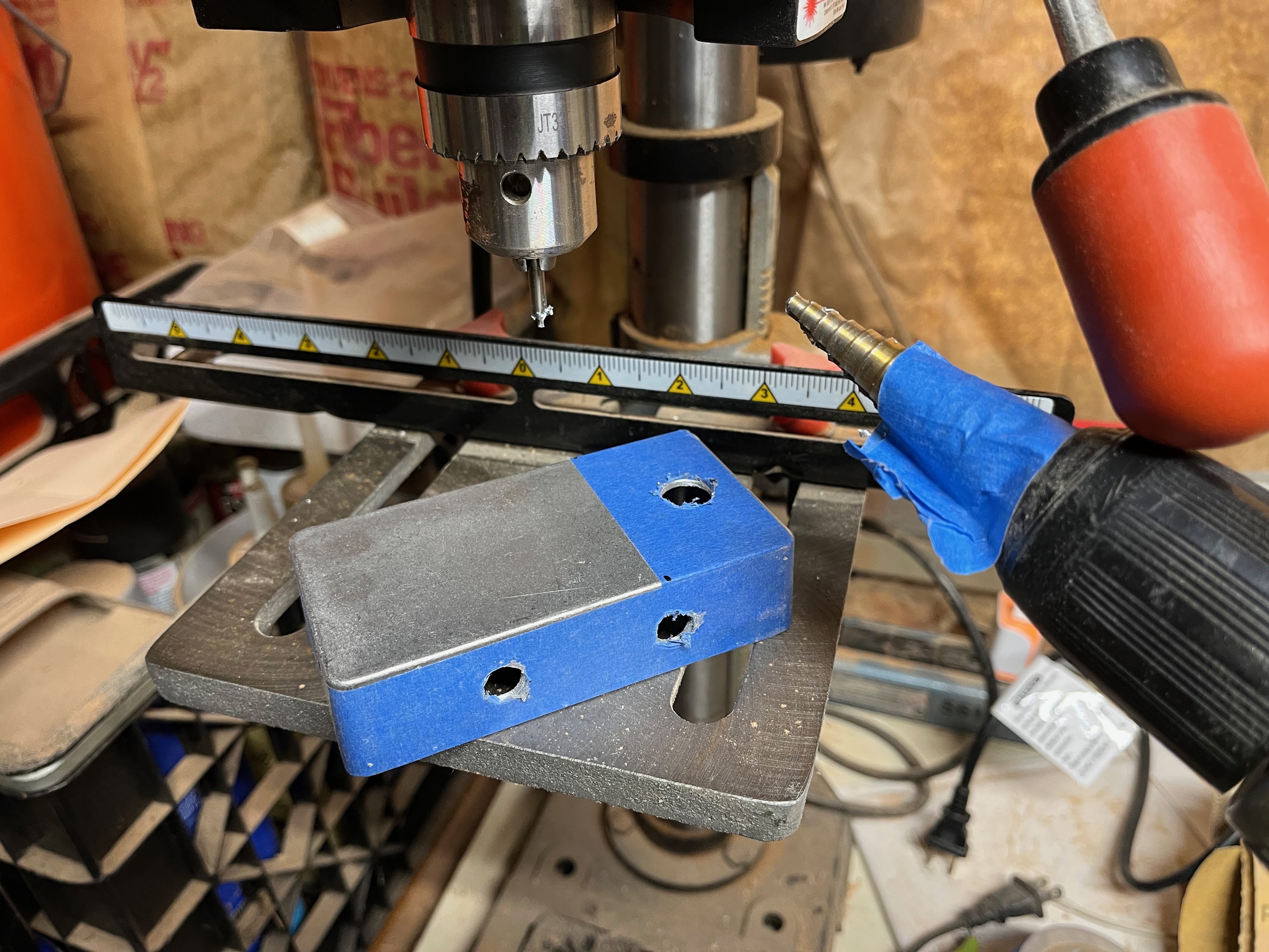
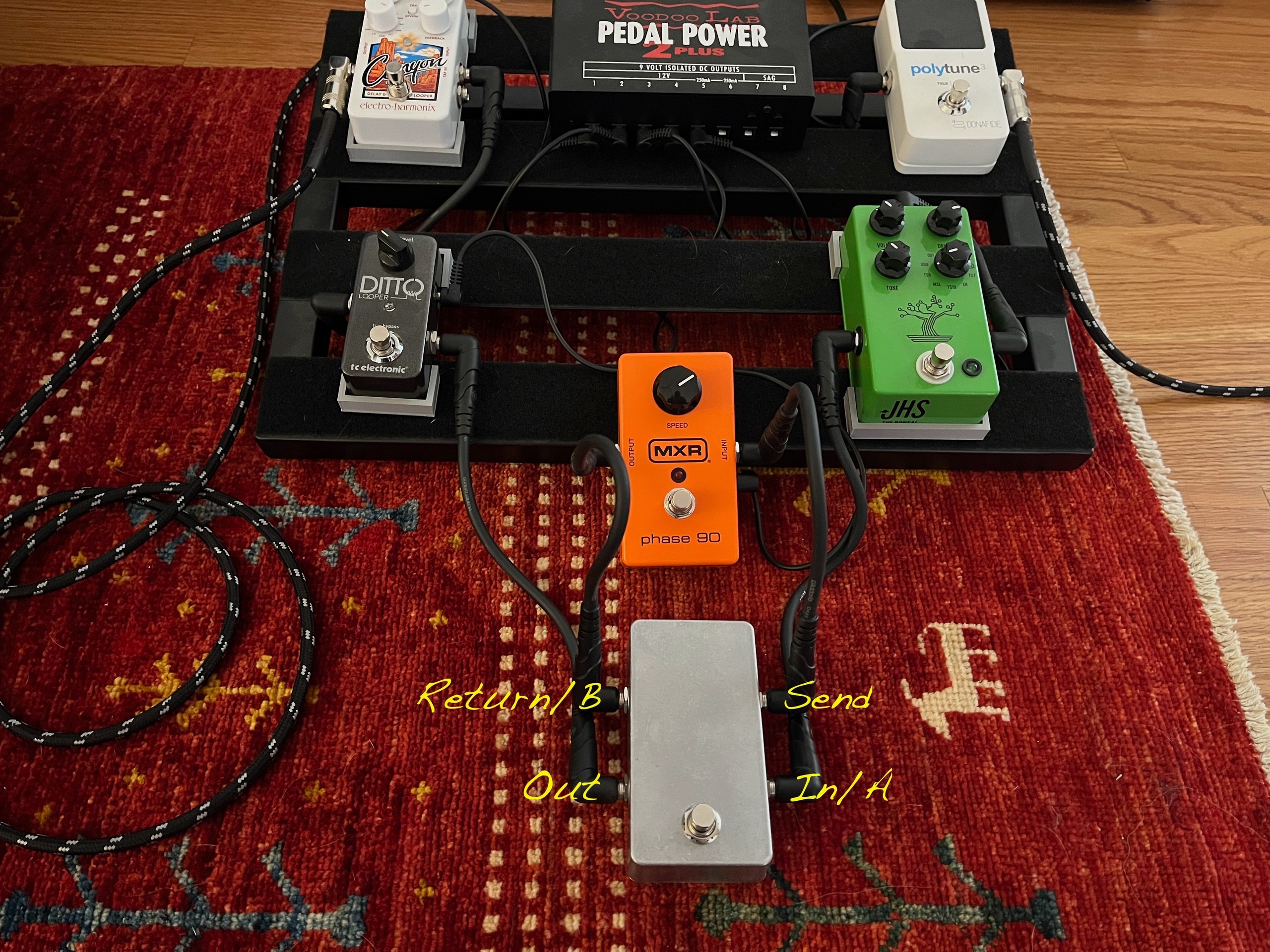
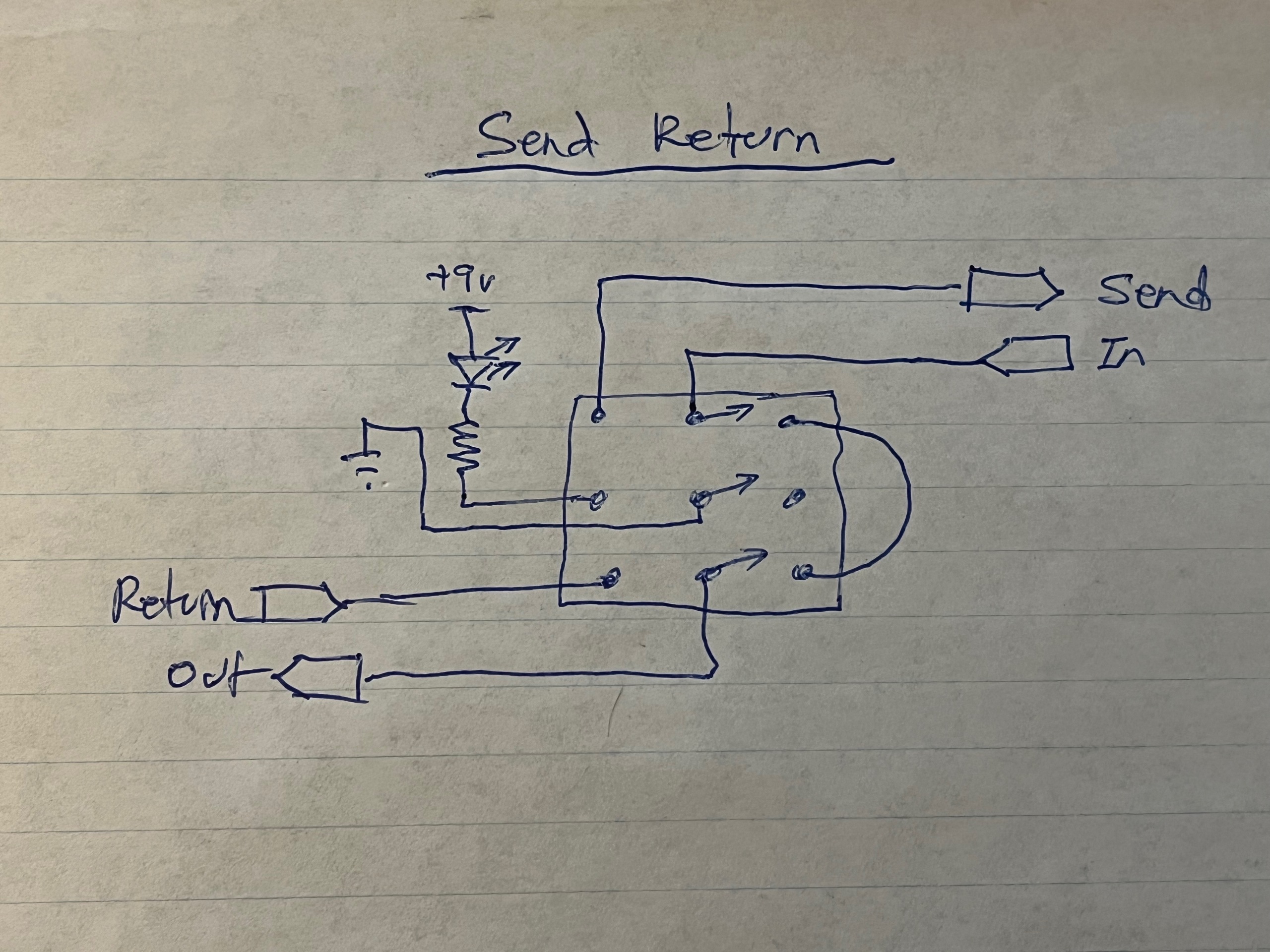
This "send return" effects loop pedal has four jacks, IN, OUT, SEND, and RETURN, and a footswitch. In one position, the footswitch is wired to route IN directly to OUT, bypassing the effects loop. In the other position, IN is routed to SEND and RETURN is routed to OUT. If SEND is patched to the input of an effects loop and RETURN is patched to its output, then the effects loop is switched into the signal path. This pedal can also be used as an A/B switch by patching signal A to IN and signal B to RETURN (the SEND jack is not used in this case).
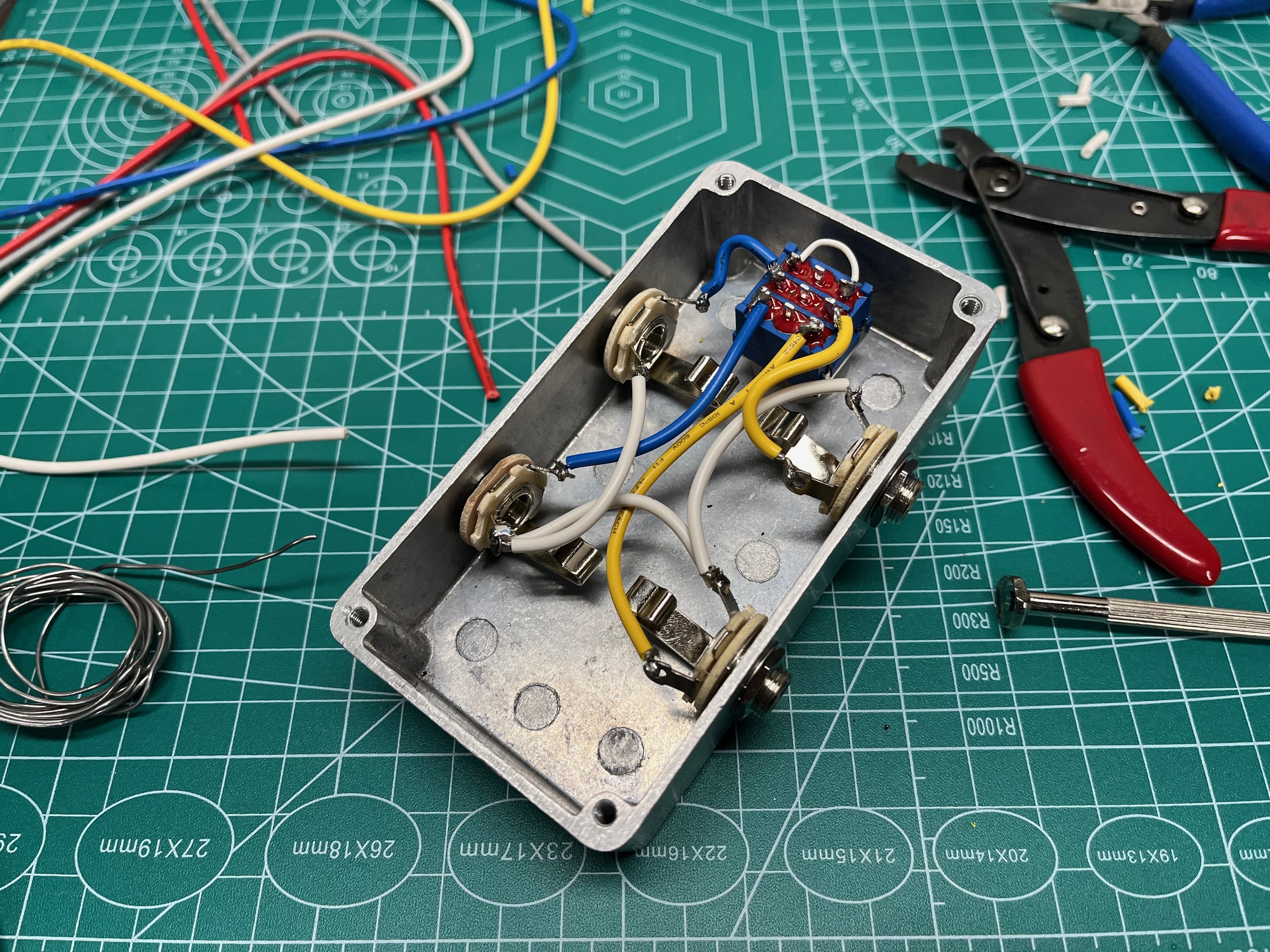
I used the bypass wiring from here https://stinkfoot.se/archives/2233. Someday I'll add the status LED, which will require a power jack, and label the case.
Breadboarding
I was now ready to start playing with transistors!
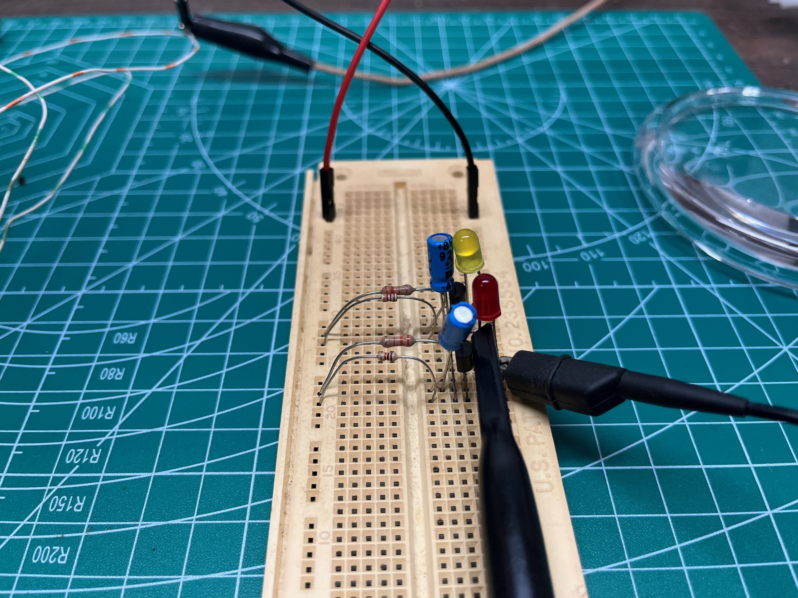
When I went looking for a breadboard I found one in an old box that already had some 2N2222s on it! A blinky LED circuit based on an astable multivibrator made with discrete components. I think it was from an old Burning Man project that I never finished.
After getting sidetracked with that for a while I took it apart and got to work on the pedal circuit.
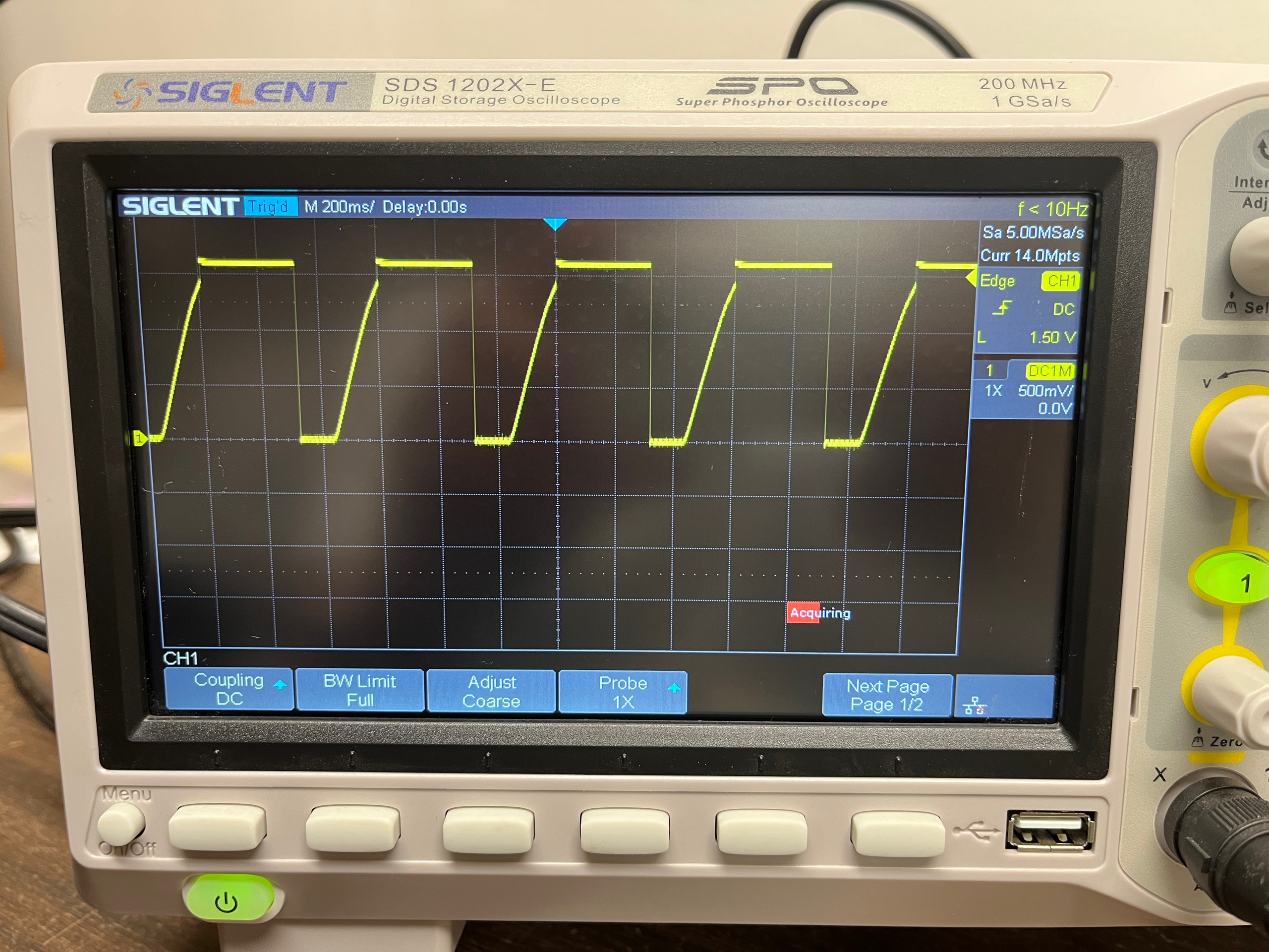
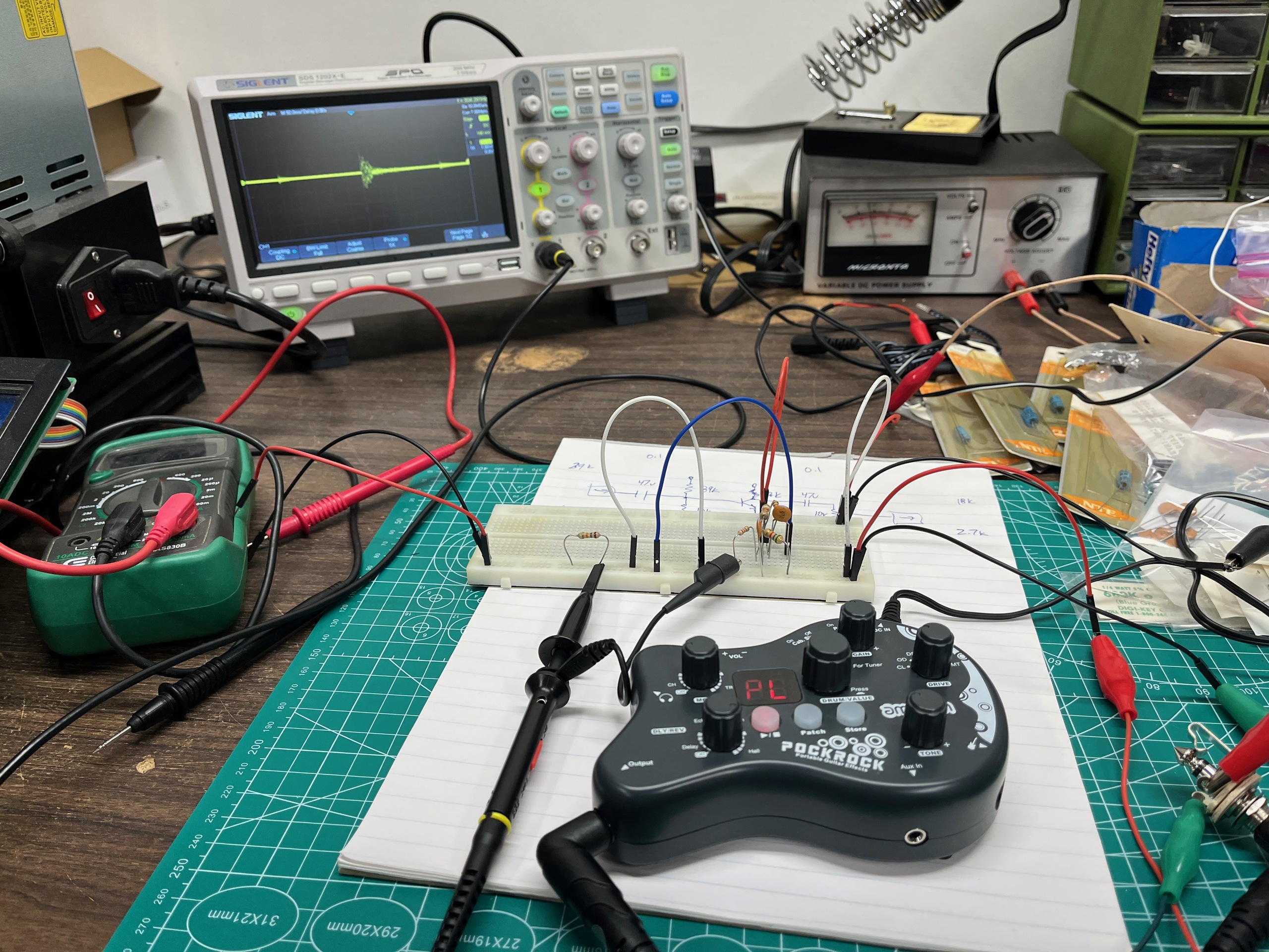
I guessed at some component values, played around until I had the transistor biased at around 4.5V, and did my best to bench test it without a signal generator... I ended up using the drum machine in a pocket practice amp as my test signal, which was far from ideal, but the circuit seemed to work.
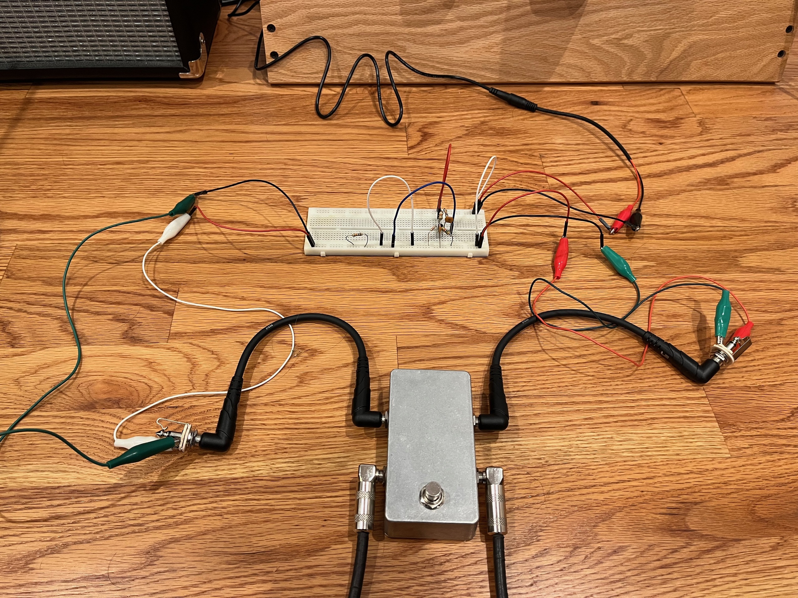
I then did a real world test, patching the breadboarded circuit in between a guitar and amp with my "send return" pedal, and was profoundly disappointed... I mean, it worked, but I was getting a lot of 60hz noise and I wasn't getting anywhere near the gain I was hoping for.
It was clear that I needed a better testing setup. I also wondered if the transistors were any good... I had gotten them at Radio Shack back in the 80s and they'd been through a lot. ;-)
Bench Testing
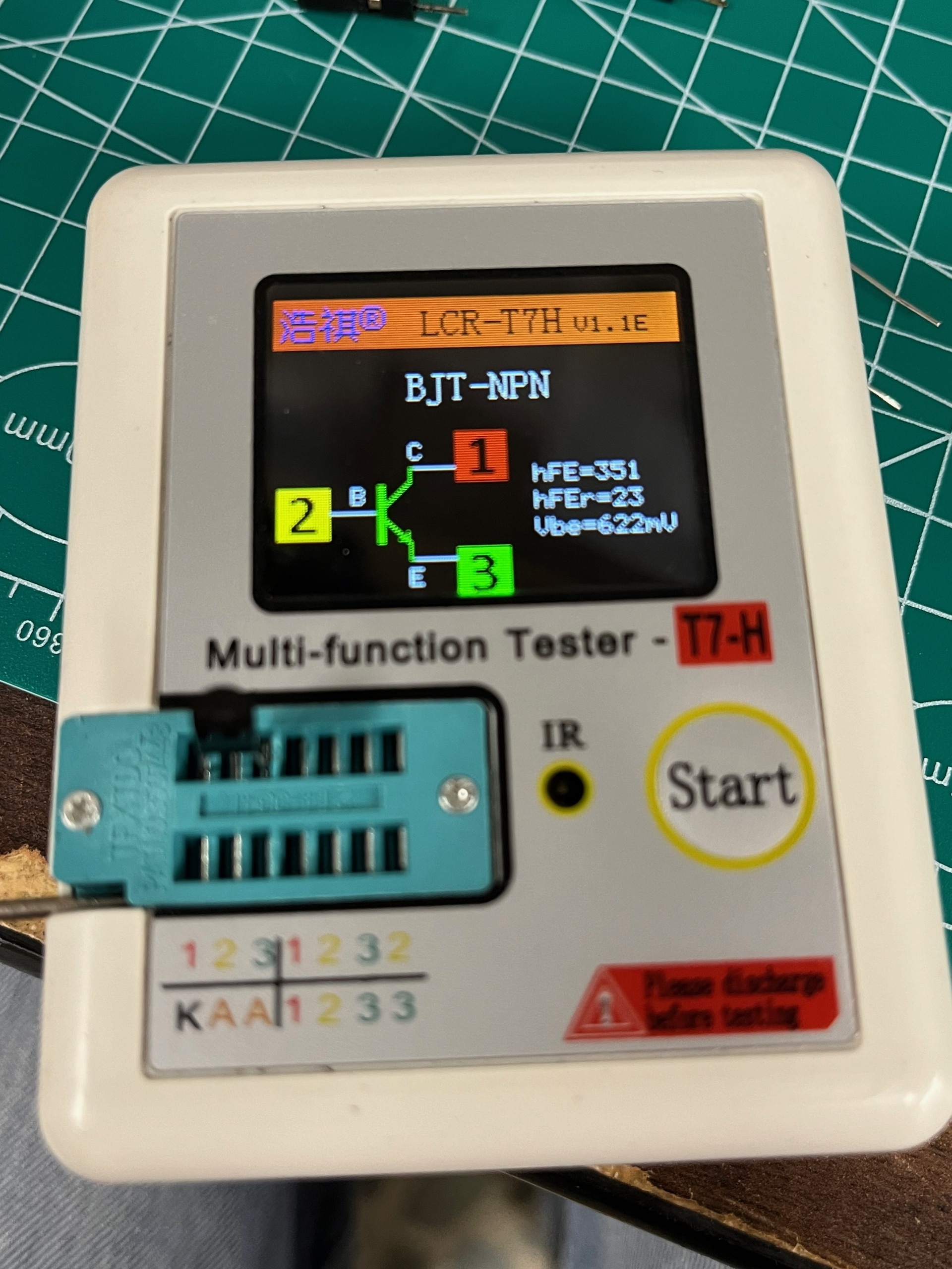
I got busy and the project went into a box. Then, one day, about six months later, a video from JHS Pedals showed up in my YouTube feed "How To Breadboard An Electro Harmonix LPB-1 Boost Pedal". In it I learned about Copper Sounds DIY Breadboards and I immediately ordered one! I also ordered a transistor tester and an audio signal generator.
When I tested my 2N2222 transistor I discovered that the pinout was REVERSED from the datasheet I was using! I was working from a 2N2222 TO-92 datasheet that showed the pin assignments as EBC and these were CBE, making them P2N2222 parts I guess. It's amazing that my first breadboarded circuit had worked at all. ;-)
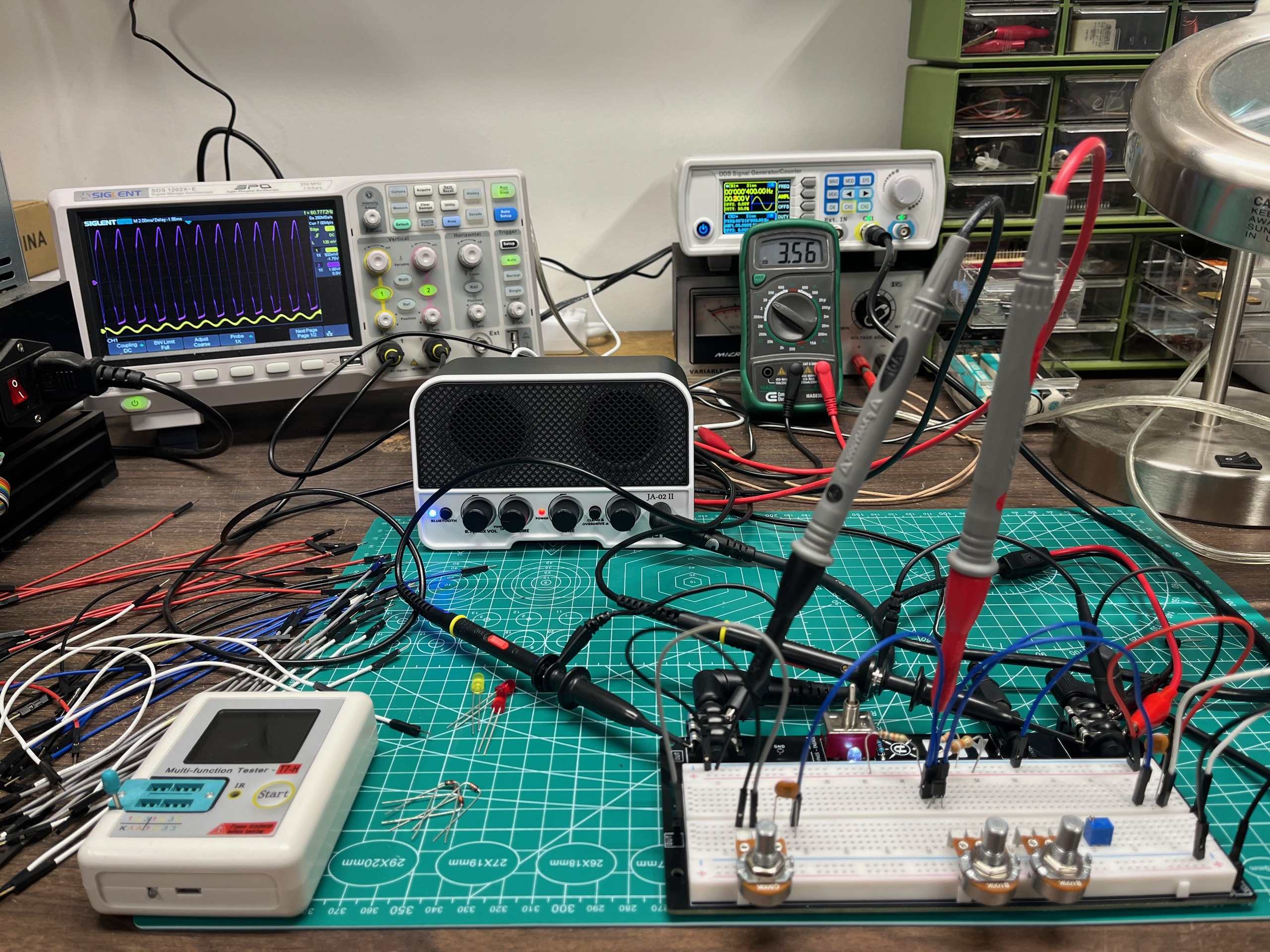
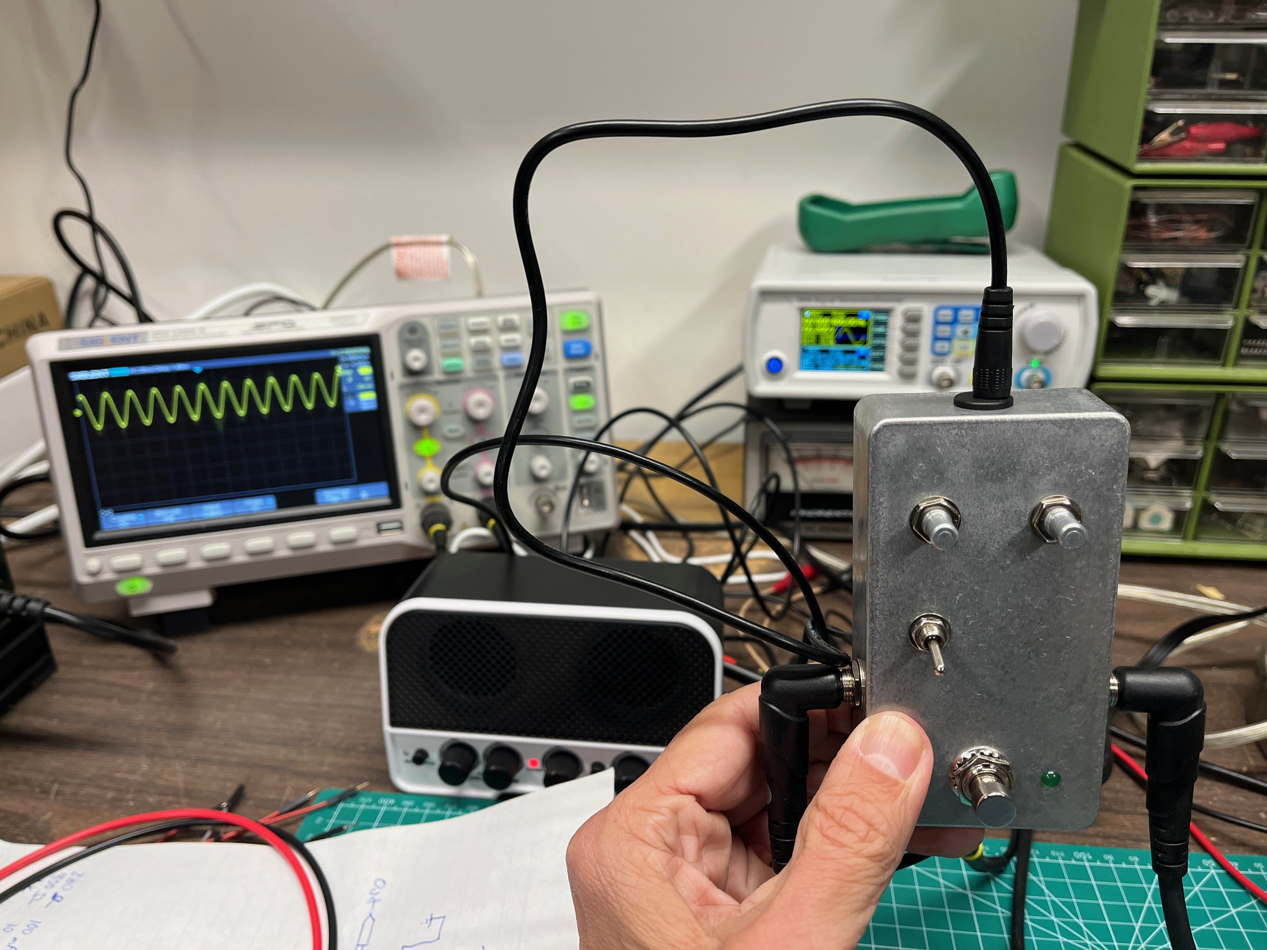
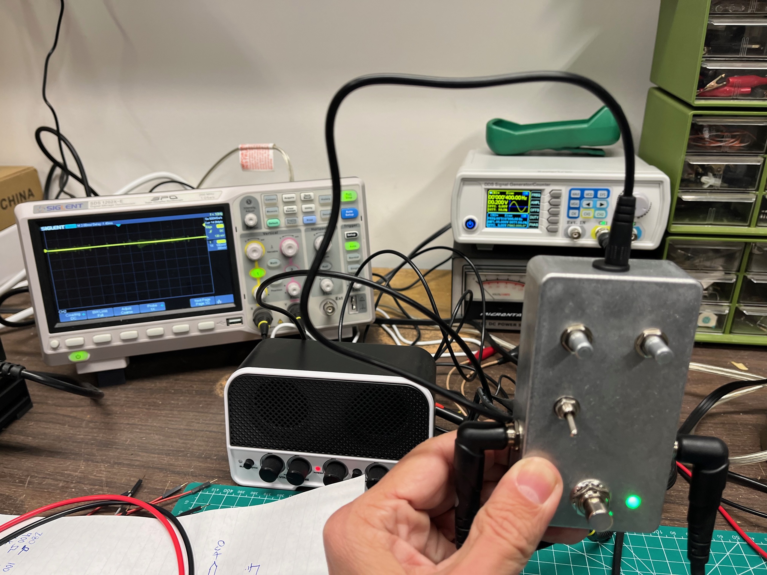
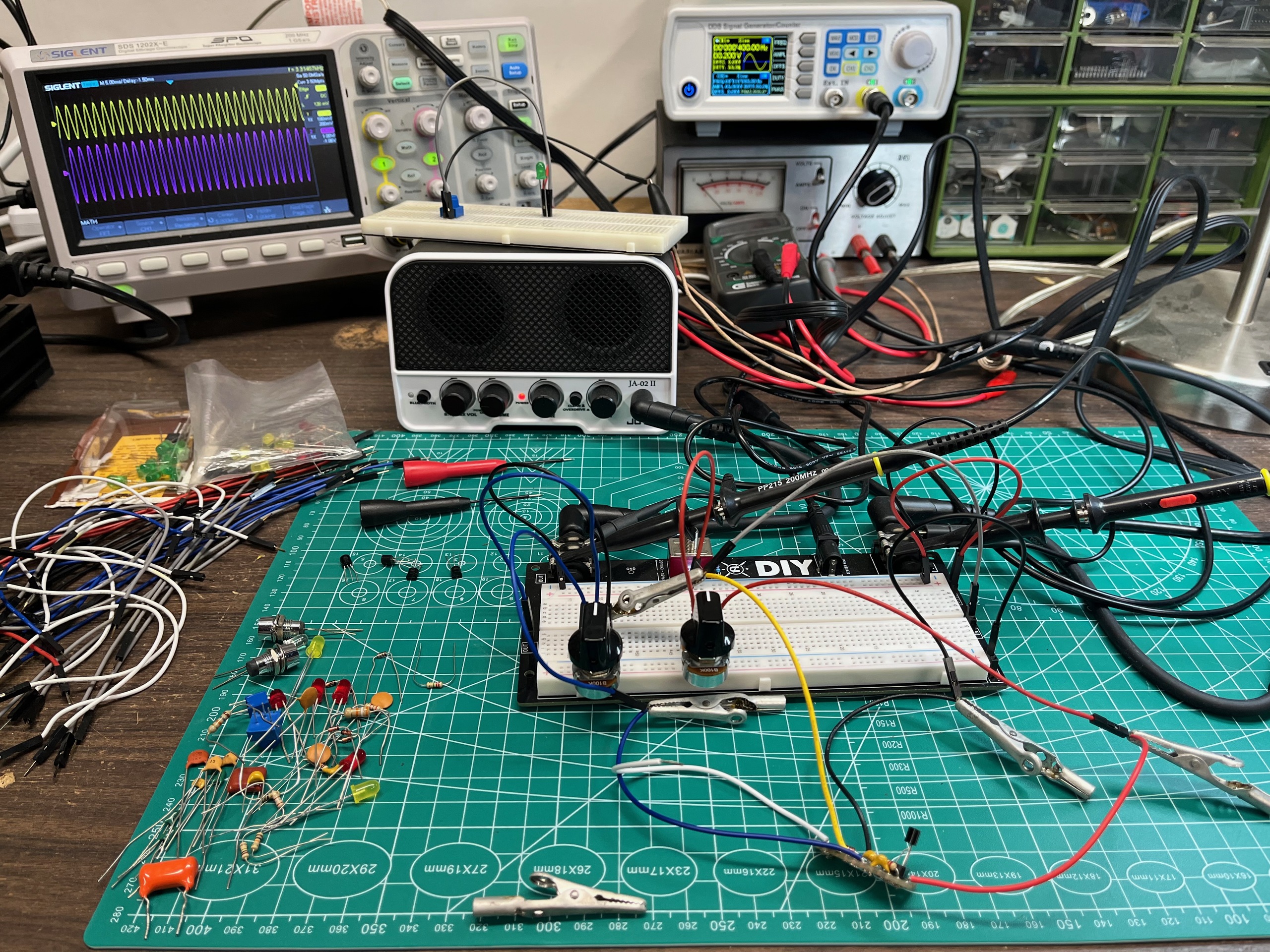
I rebuilt the circuit on the Copper Sounds DIY Breadboard, getting the transistor pinout right this time, and used my new signal generator to test it. I tracked the bias voltage with a multimeter and compared the input and output signals on my two channel oscilloscope. I used the effects loop pedal in its A/B mode to switch between the signal generator and a guitar.
With this setup I was able to experiment with various component values and biasing schemes and see how the performance of the circuit changed. I replaced the biasing resistors with trim pots to see how the circuit behaved at different bias voltages, replaced the collector resistor with a gain pot to see how much useful range in gain I could get, and tried eliminating the emitter resistor completely for maximum gain (connecting the emitter directly to ground). I also experimented with using feedback biasing instead of voltage divider biasing, which seemed to improve the stability of the circuit, and with 1N914 and LED clipping diodes.
I settled on this circuit with a single stage 2N2222 common emitter amplifier using feedback biasing, gain and volume pots, and diode clipping with 1N914 diodes (which I planned to make optional with a switch). I had several 2N2222 parts with an hFE of 200 and one outlier part with an hFE over 300, but I found that they all performed about the same in the circuit.
The Build
Happy with the circuit, I was now ready to build it into an enclosure!
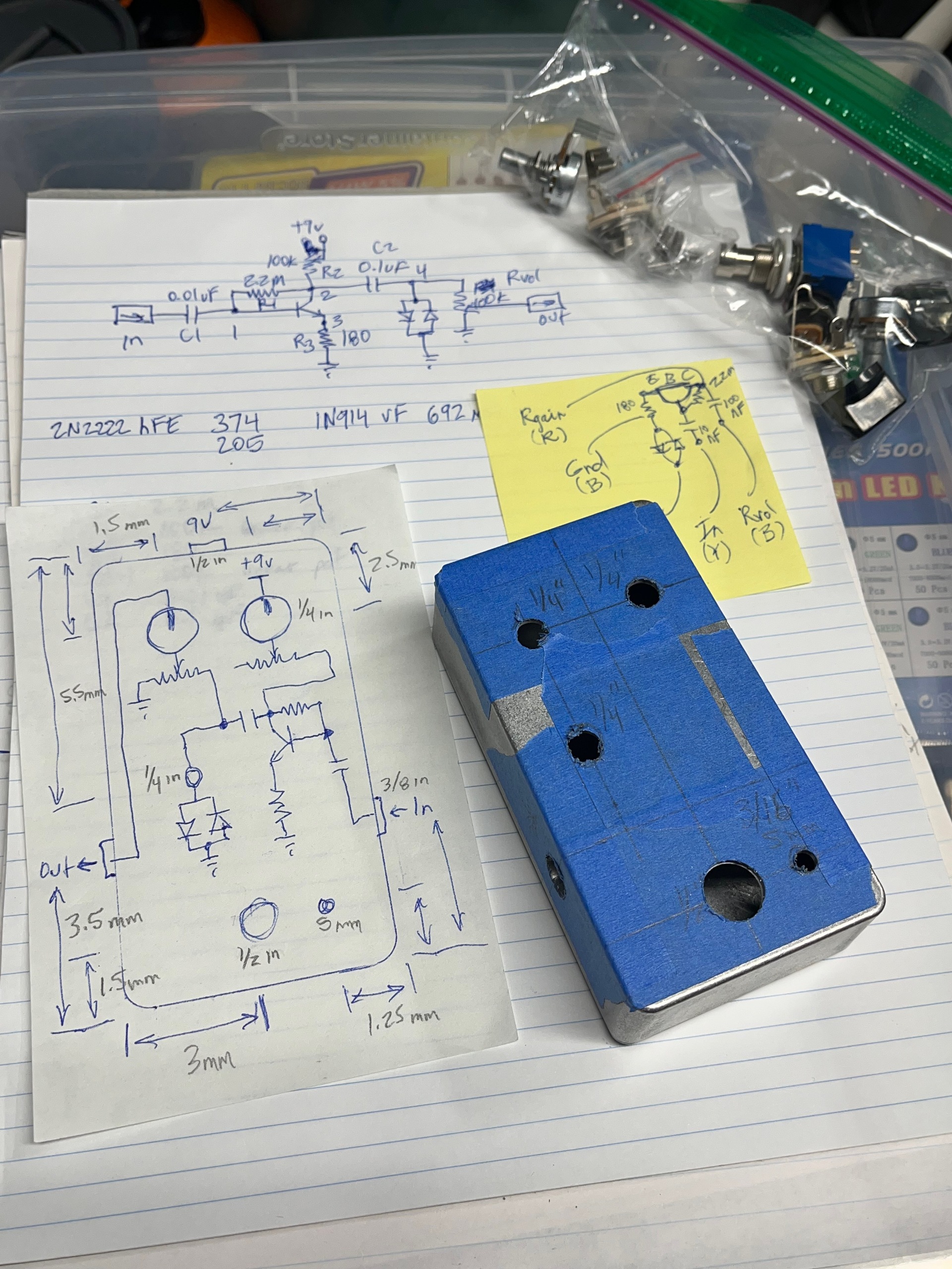
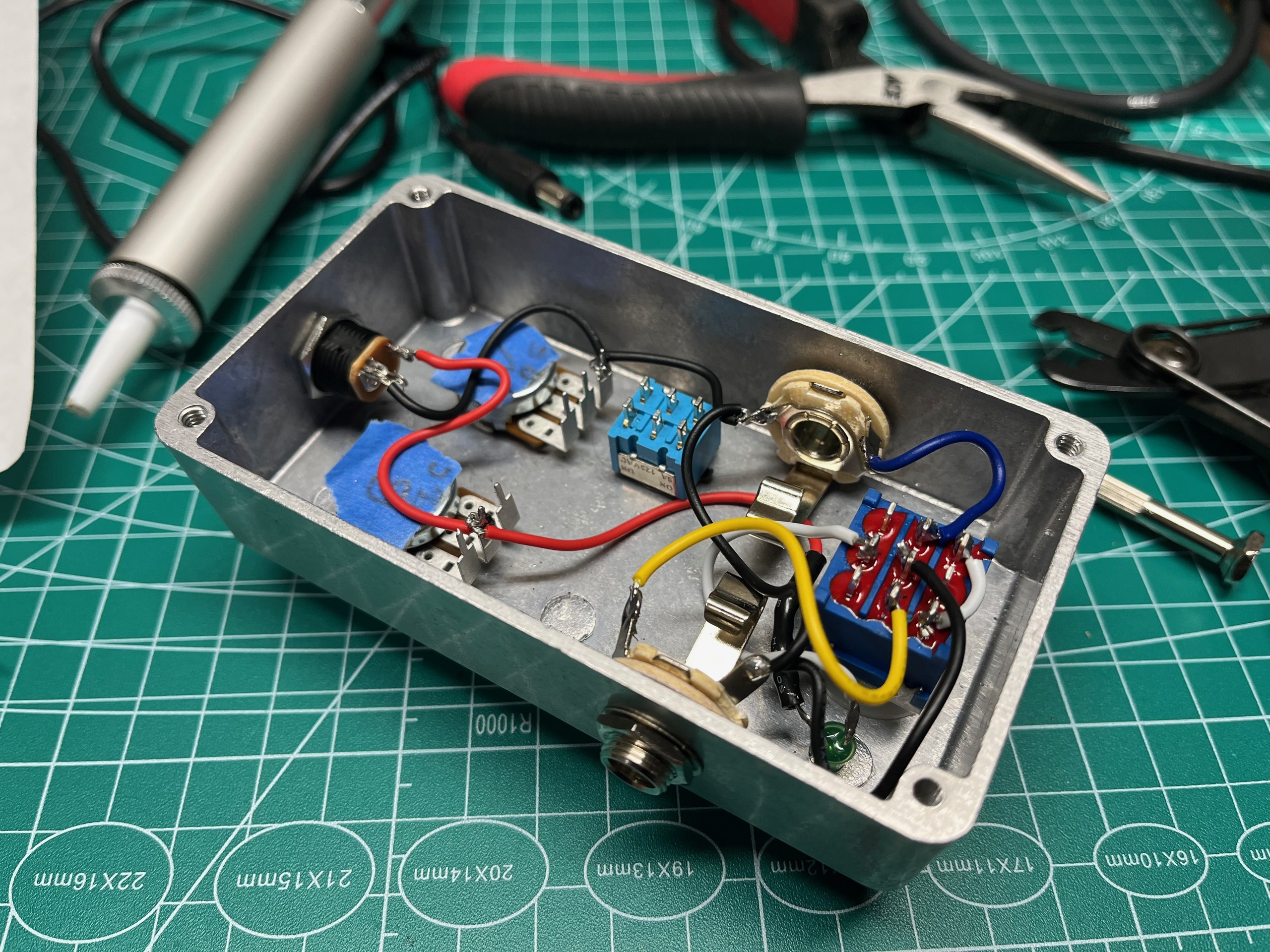
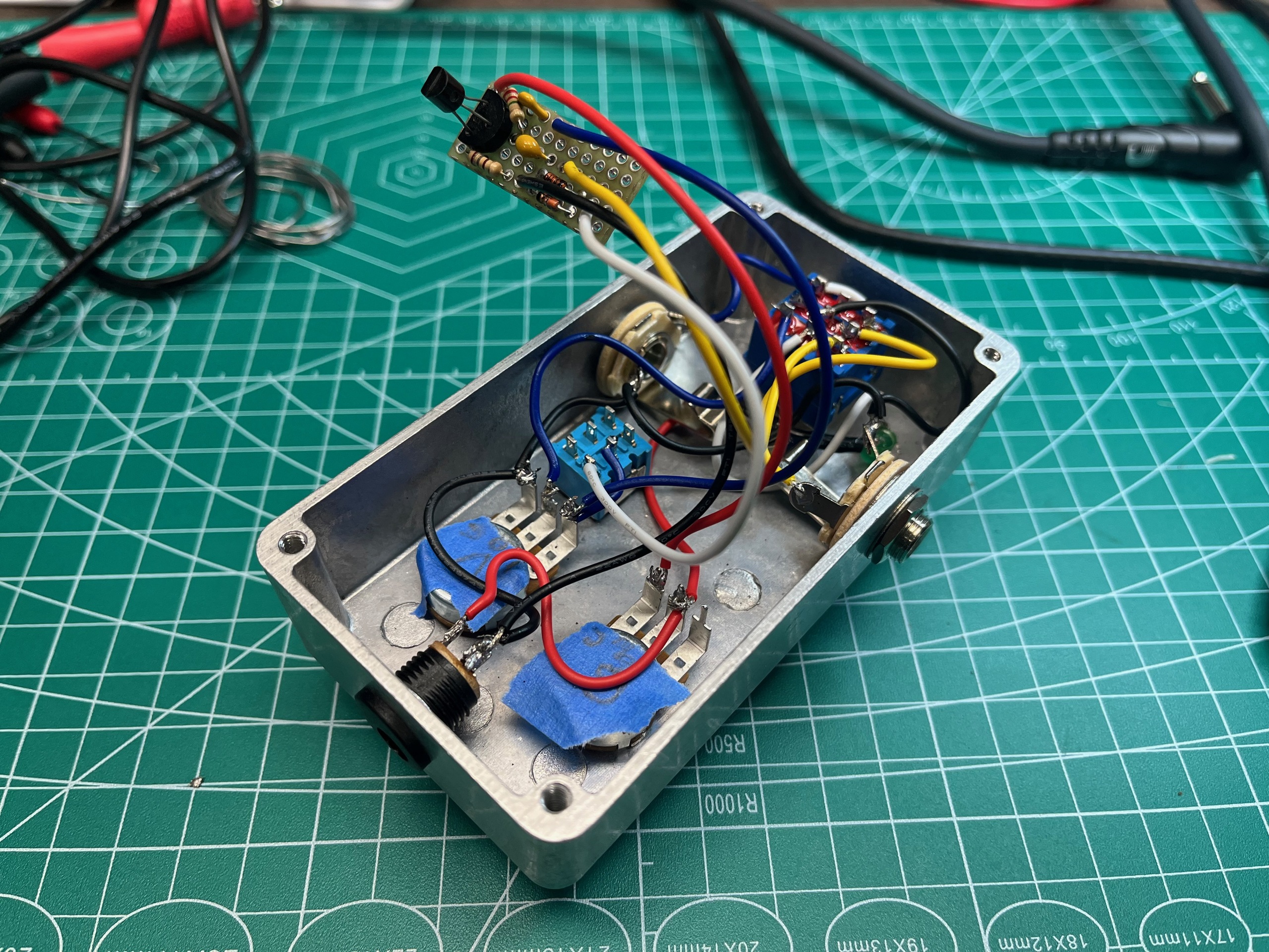
I started by installing the jacks, pots, and switches and wiring the bypass circuit.
I then tested the bypass circuit and status LED.
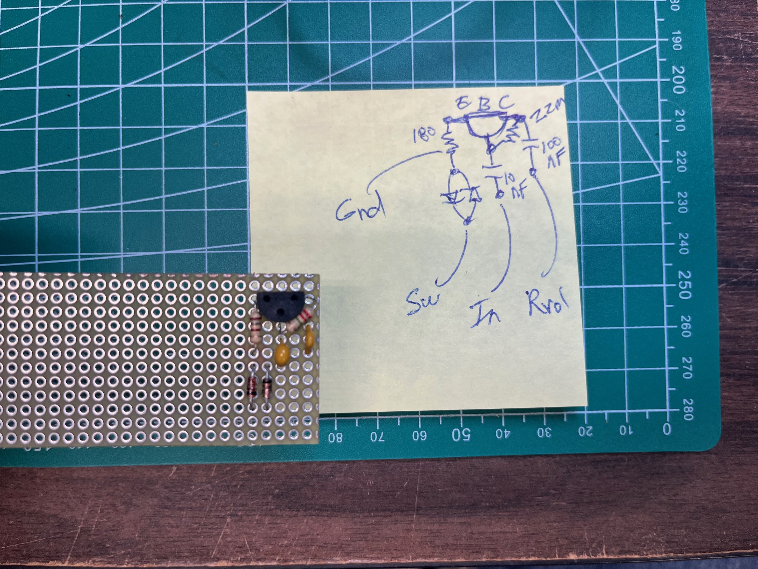
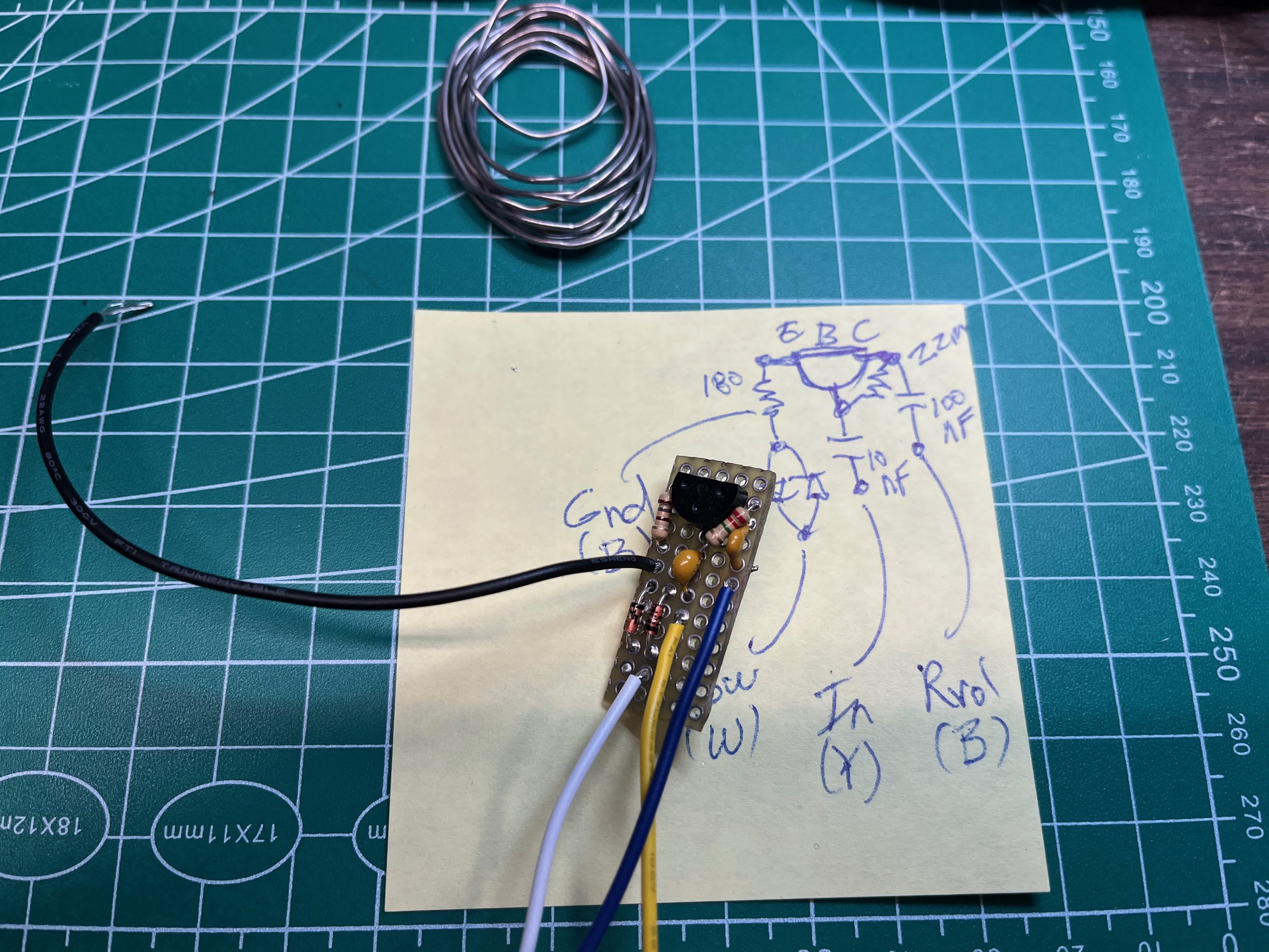
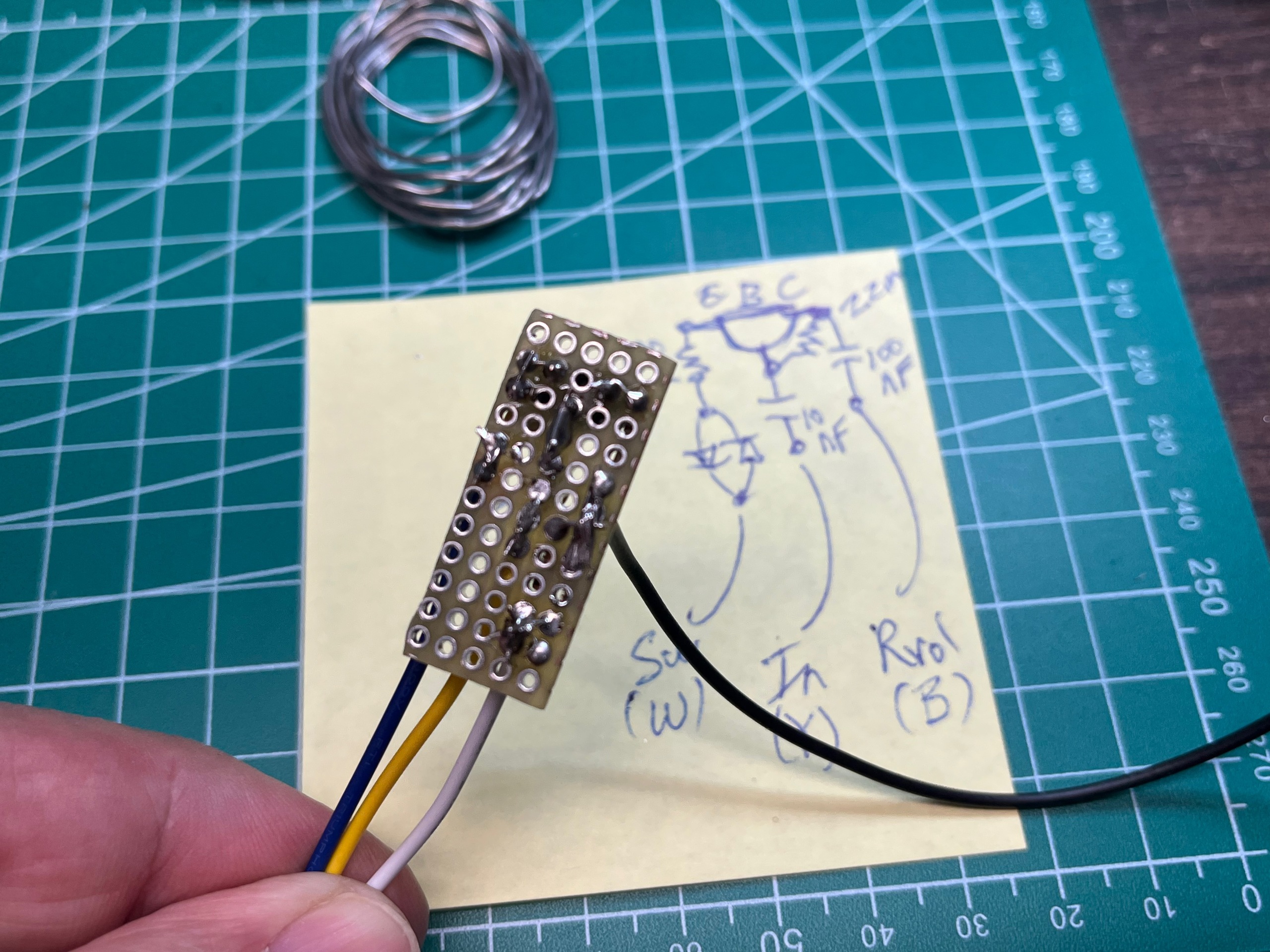
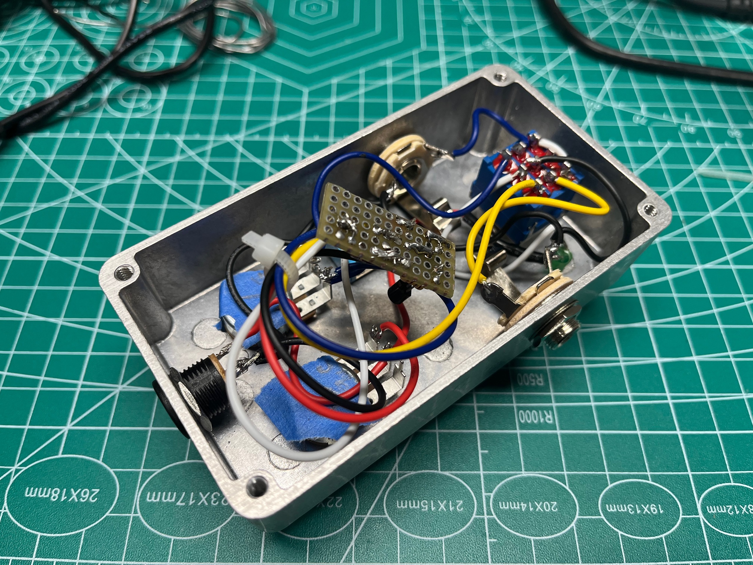
Next, I wired the circuit board and tested it.
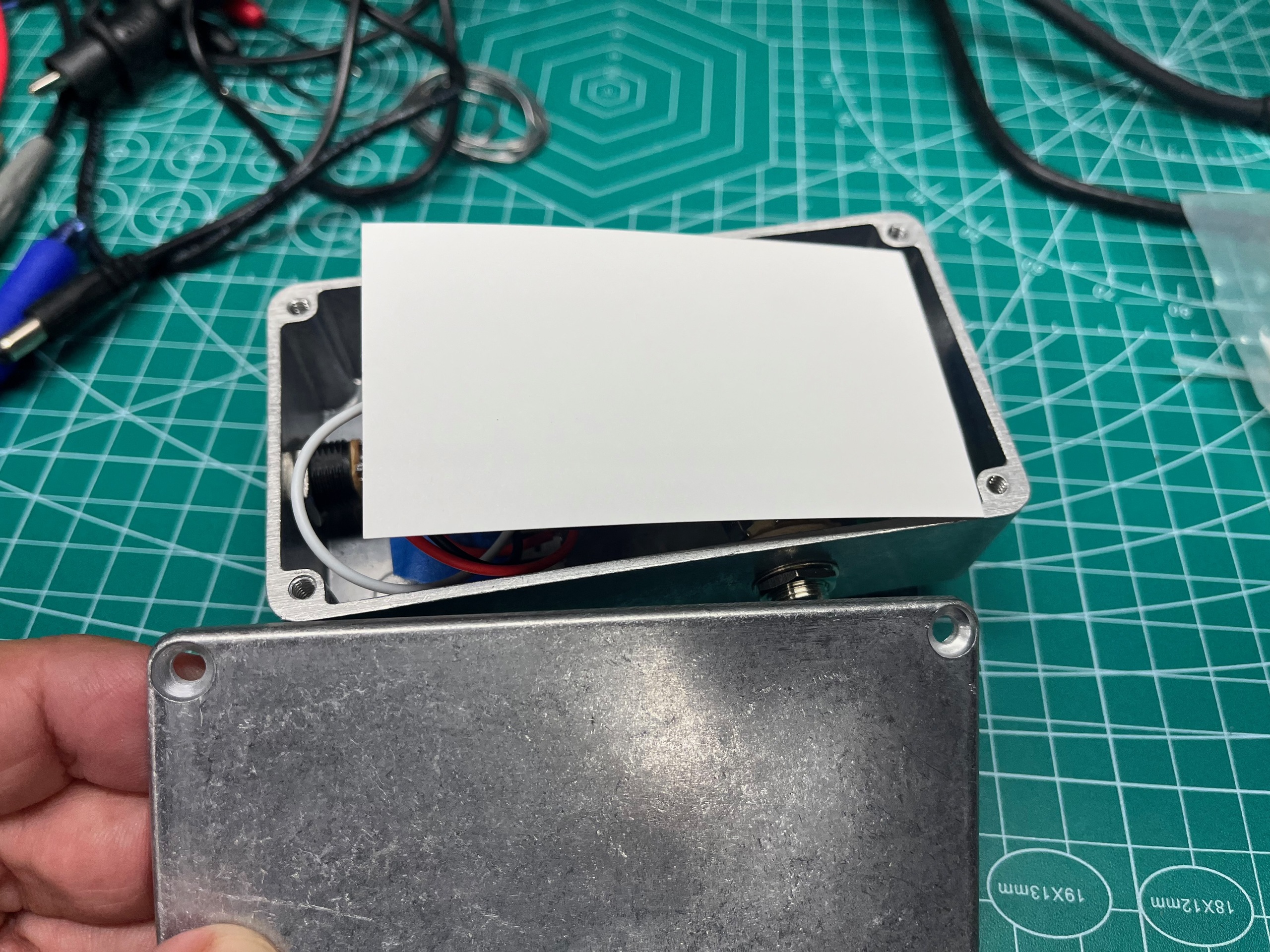
The circuit board worked, so I wired it into the box and closed it up, using a business card as an insulator.
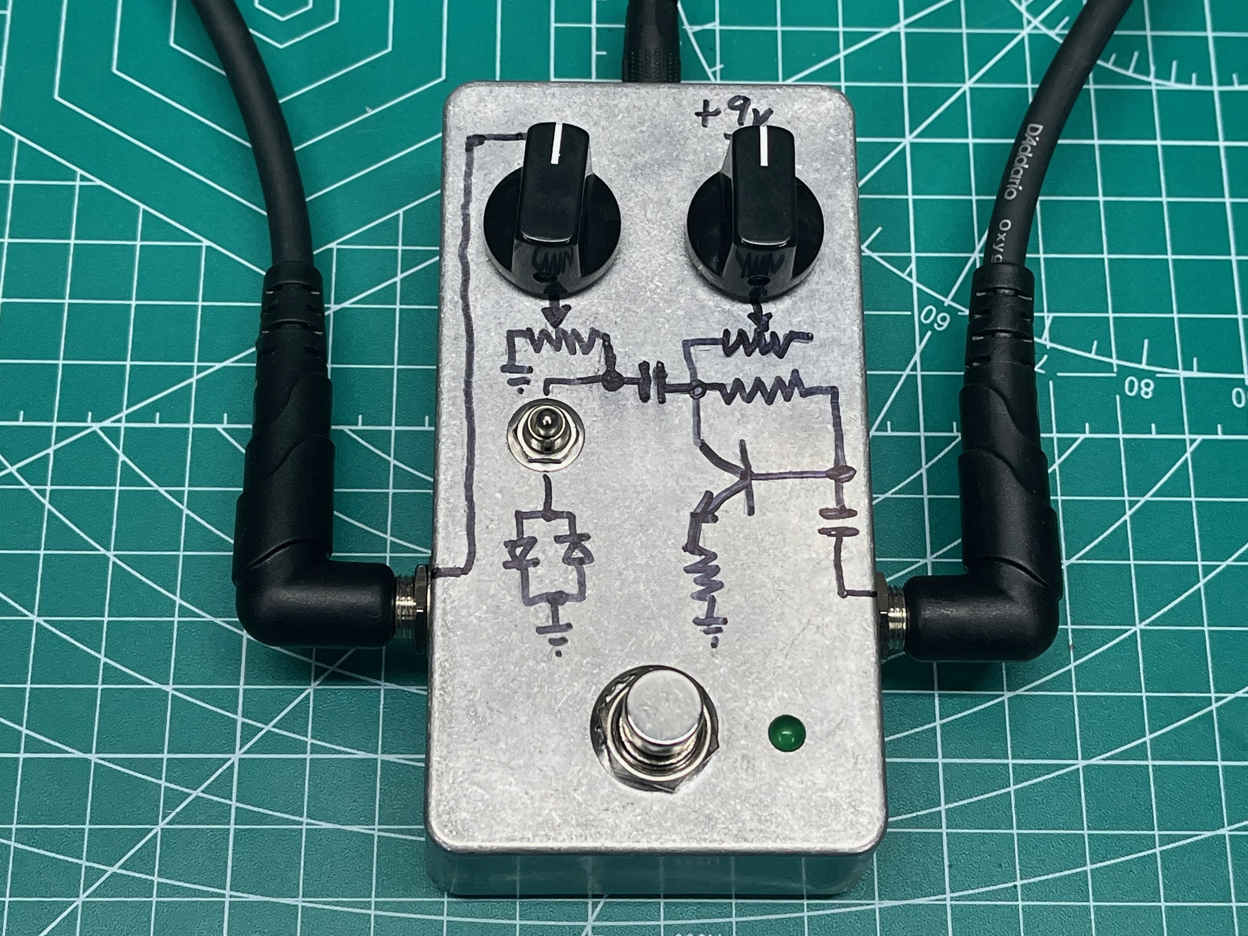
Finally, I added some artwork with a sharpie: the circuit schematic overlayed onto the jacks, pots, and clipping diode switch. Note that the signal flows from right to left in a guitar pedal, so the schematic is reversed from the normal convention.
Demo
Here's some sample audio:
-
guitar volume 10, pedal bypassed
-
guitar volume 10, pedal volume and gain knobs at 12 O'Clock, diode clipping off
-
guitar volume 10, pedal volume and gain knobs at 12 O'Clock, diode clipping on
-
guitar volume 5, pedal volume and gain knobs at 12 O'Clock, diode clipping on
Simulation
I used SPICE circuit simulation during the breadboarding process to better understand some of the design choices.
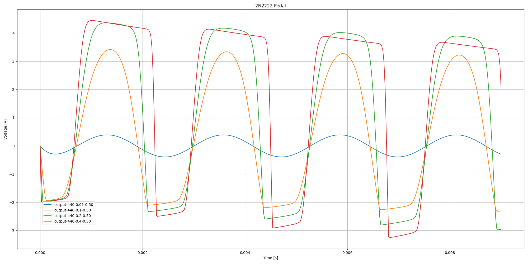
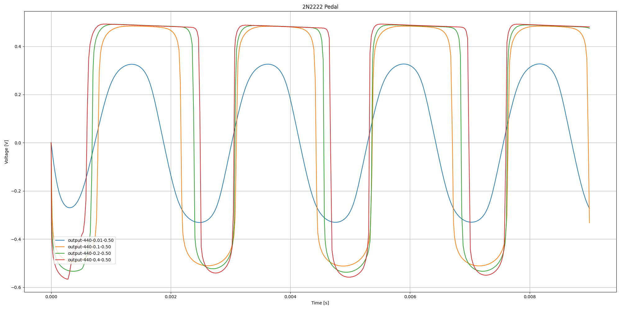
These plots show how the final circuit responds to a range of input signal amplitudes at the 12 O'Clock gain position, first with and then without the clipping diodes.
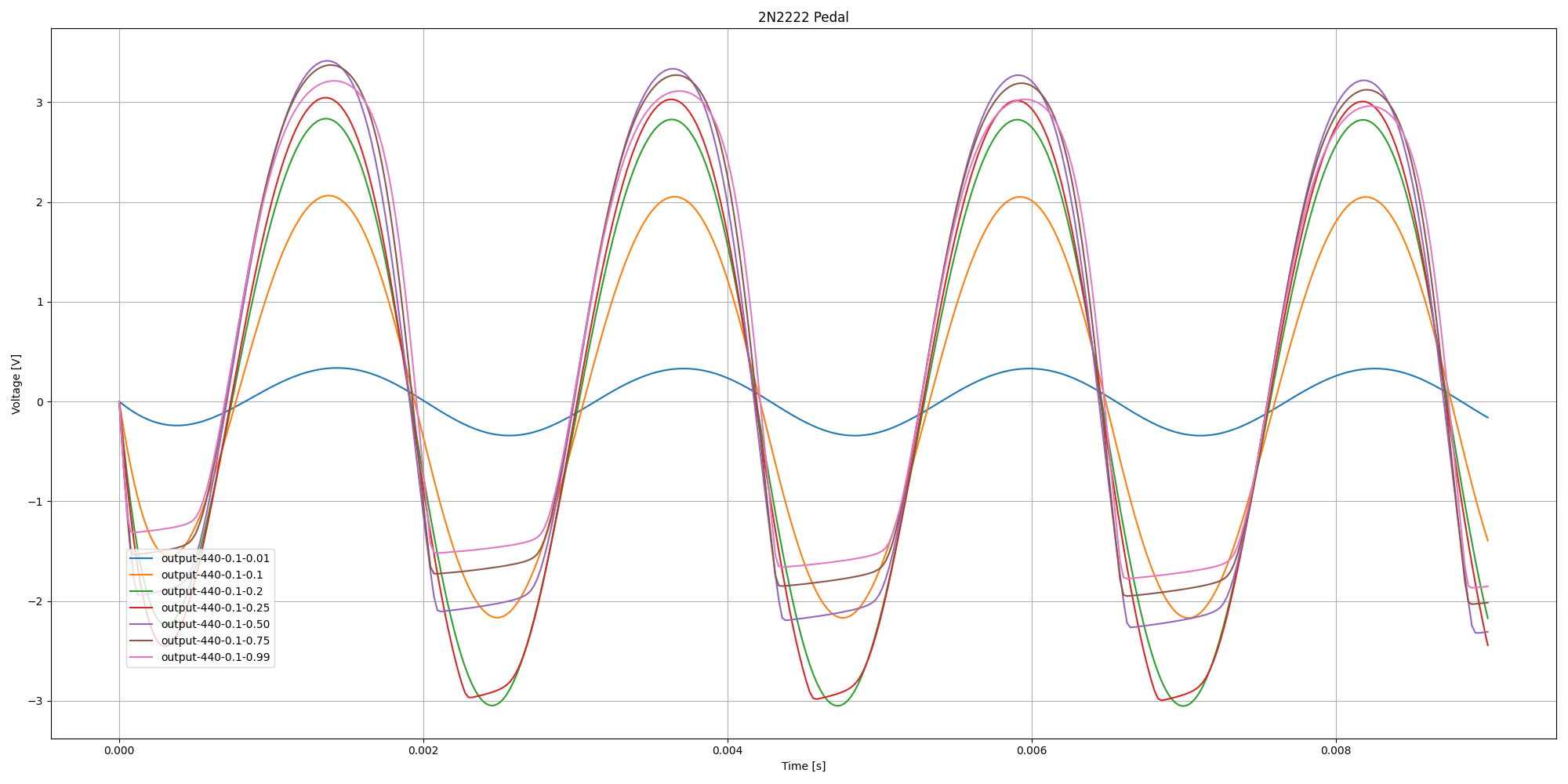
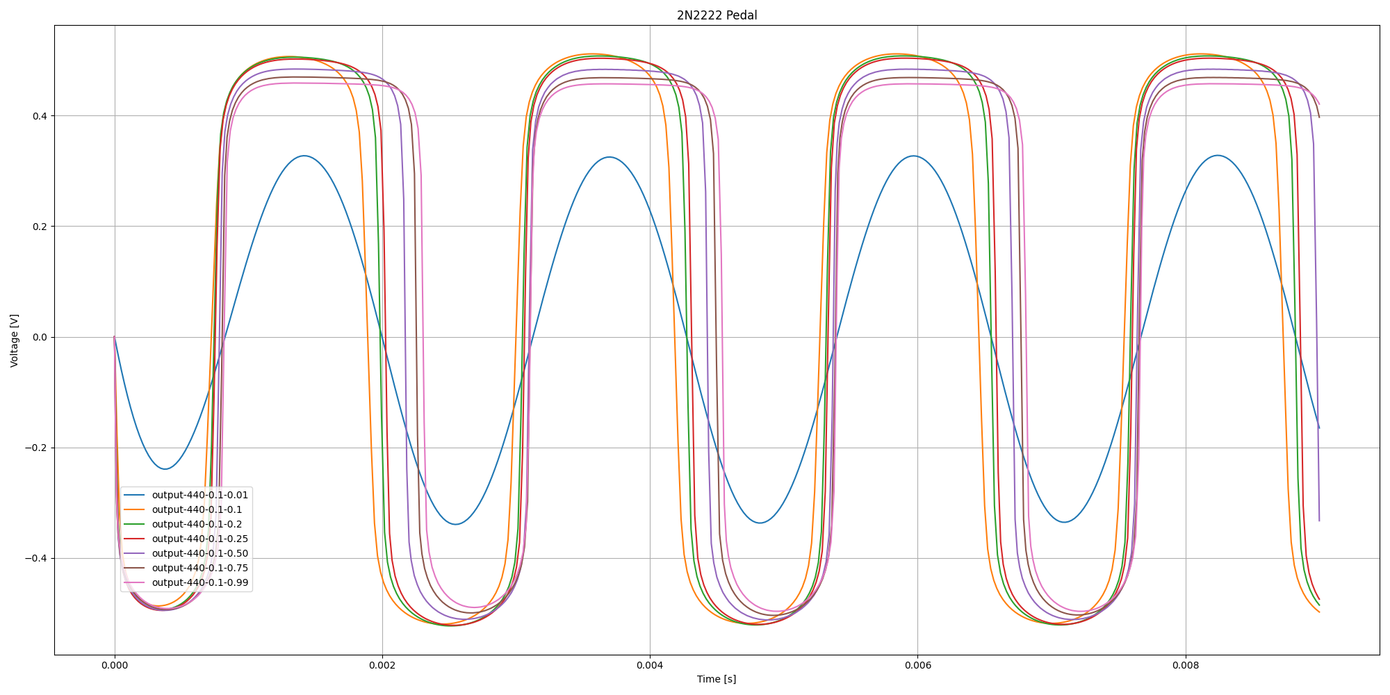
These plots show how the final circuit responds as the gain pot is varied from min to max for a modest input signal amplitude, first with and then without the clipping diodes.
More Info
Historical single transistor amplifier (boost) pedals include
- The 1965 Dallas Rangemaster Treble Booster, a single stage common emitter amplifier using a PNP BJT (schematic and analysis here)
- The 1969 Electro-Harmonix LPB-1 Linear Power Booster, a single stage common emitter amplifier using a NPN BJT (schematic and analysis here)
- The 1976 Electra MPC 5 Power Overdrive, a single stage common emitter amplifier using a NPN BJT with collector feedback biasing, which is also the basis for a popular DIY distortion circuit that dates back to USENET (schematic here and here)
Also, if you're interested in building your own pedal, I highly recommend Josh Scott's "Short Circuit" videos on the JHS YouTube channel
